![]()

200TDi into Defender - some useful information
Guide for DIY fitting - by Glencoyne Engineering
![]()
![]()
![]()
![]()
![]()
![]()
![]()
![]()
![]()
Preparing your new engine
I always like to prepare the new engine as far as possible before removing the old one. This minimises the amount of time that the vehicle sits around immobile. Engine prep will probably take you the best part of a day.
First step is to strip off all the bits that you don't need or that get in the way. Remove any wiring (apart from the glow plug wires), coolant hoses, oil cooler pipes etc. Remove the viscous fan - ideally while the fan belt is still in place. Use a 32mm viscous coupling spanner and give it a clout with a hammer (thread undoes clockwise from the front). These couplings are very tight and sometimes I have had to resort to a hammer and chisel to shock it free. Remove the engine mounts, starter, alternator, power steering pump and clutch. Now is a good time to clean the engine. If using a jetwash make sure you seal up all the places where water might get in.
If you are planning to change the timing belt, now is an ideal time. You will need to remove the alternator/PAS pump bracket to get the front cover off. I always change the timing belt, tensioner, idler and front crank seal on every conversion I do. I have seen quite a few engines where the old timing belt is about ready to let go. Remember that an old Disco could have been run for the last few years of its life with very little maintenance. Click here for more information on timing belt replacement.
Flywheel housing
Your next task is to prepare the flywheel housing so that it will mate with the gearbox. The Disco housing has four long M10 bolts which go through the flywheel housing and screw into the cast alloy stiffening plate between the engine block and sump pan. I suspect these bolts are quite important in reducing vibration and preventing undue stress at the join between engine and gearbox, as well as preventing the flywheel housing from pulling away from the back of the block and leaking oil. However, the Defender bellhousing does not have holes for these four bolts - instead it has holes for three studs, which are not present on the Discovery flywheel housing. There is another stud missing on the right hand side - four studs missing out of a total of eleven. The Disco housing also has an extra stud at around the seven o'clock position which needs to come out and two steel dowels which need to be removed. Many people have ignored this problem and simply bolted the Disco motor to the Defender bellhousing with no ill effects so far (although it might explain why so many TDi conversions seem to leak oil from the back of the engine). But if you want to do a proper job, I strongly recommend that you do something about these problems.
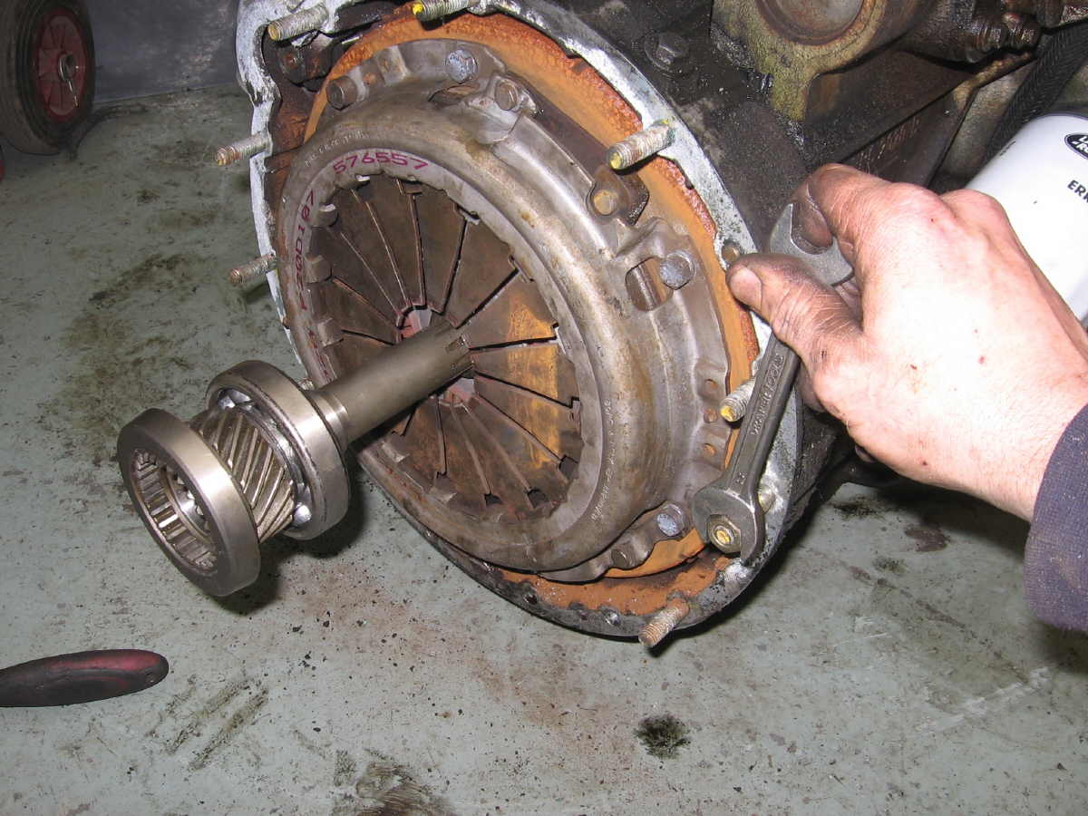
First, remove the flywheel from your Discovery engine, followed by the flywheel housing. There is a stud in the flywheel housing at about the eight o'clock position which needs to be removed and there may also be two steel dowels in the rear face of the flywheel housing (one next to my thumb in the photo below). These must be removed if present. To remove studs, simply run two nuts onto the stud, then turn them against each other to lock them together. If you turn the innermost nut anti-clockwise with a spanner, the stud should now unscrew from the flywheel housing. The dowels usually pull out quite easily with Mole grips. If they are really stuck you can drill them or grind them flat.
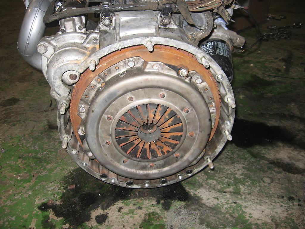
Now you need to counterbore the four holes in the bottom of the flywheel housing to take M10 x 80 Allen bolts, then drill and tap the housing M10 to take the four extra studs (one at around three o'clock, then three more at the bottom). The housing has blind holes in exactly the right places for the four studs. The stud above the hole at three o'clock needs to be swapped over to the new hole. The photo below shows the housing modified and fitted to the engine with all studs and bolts in place apart from the three holes at the bottom, where I normally use M10 x 30 bolts rather than studs. Note the four Allen bolts at the bottom of the flywheel housing, which go through the housing and into the block stiffener:
To do this properly you really need a pillar drill, an M10 counterbore and an M10 x1.5 thread cutting tap, as well as the Allen bolts which are hard to buy in small quantities. Also you need to fit a new oil seal, and these can be difficult to fit without distorting them unless you have the right tools. For this reason I can now modify your flywheel housing for you. This comes with the four holes counterbored for the long through bolts, extra stud holes drilled and tapped, all bolts, studs, nuts and lockwashers as in the photo immediately above and a new oil seal carefully fitted using a hydraulic press. Price is £65 (including postage) - simply send your flywheel housing along with your return address and a cheque to Glencoyne Engineering, Unit 10 Heath Road Industrial Estate, Banham, Norfolk NR16 2HS. Or let me have your email and I will send you an invoice with payment details. I can usually turn these round in a couple of days.
Refit the modified flywheel housing to the block with a new gasket ERR1440 if required. (Some early TDis used RTV sealant instead of a gasket). You need to be very careful when fitting it, to avoid damaging the new crank seal. The seal has a plastic sleeve inside it which fits over the end of the crankshaft to protect the lip of the seal. Position the flywheel housing on the two studs, making sure the plastic sleeve is securely located over the crankshaft end, then use tighten the housing-to-block bolts slowly and progressively. Make sure the housing is pulled onto the block squarely and that the sleeve does not slip out of position before the seal is safely in position over the end of the crankshaft. Discard the plastic sleeve after fitting. Now fit the flywheel - use Loctite on the bolt threads and do them up to the specified torque. Finally refit the starter motor.
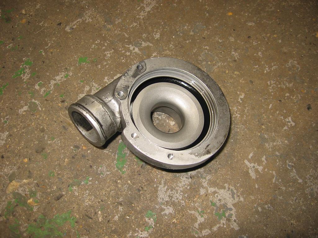
Turbo housing
The Disco engine has a low-mounted turbo whose exit is very close to the inner wing when fitted to a Defender. It is possible to buy pipe kits to connect the turbo to the intercooler but I have found that, however much care you take, these always rub on the inner wing which is not ideal as they will eventually rub through. Also a low-mounted intercooler pipe will make the area between the power steering pump and inner wing very crowded indeed, and you will have a lot of fun trying to fit air intake pipe, intercooler pipe and power steering pipe into the available space. So I prefer to 'clock' the turbo. This involves rotating the turbo housing through 90 degrees so that the outlet points up and out. You can then loop the intercooler pipe over the top of the alternator and down to the bottom of the intercooler. It may sound a bit daunting but it isn't that difficult.
Step 1 - remove the wastegate actuator. This has a C clip securing the pushrod to the wastegate arm and two M6 bolts attaching it to the turbo housing. Now mark the turbo housing with a dot punch next to an easily identified point on the main turbo body. The union for the oil feed pipe is an ideal reference point.
Step 2 - remove the turbo housing from the body. There is a large, strong circlip between the housing and body. Remove this (can be tricky, will need big strong circlip pliers) and the housing will come away.
Step 3 - drill and tap two new M6 holes 90 degrees anticlockwise from the existing ones. Use a protractor, mark very carefully and double check before you start drilling.
Turbo housing with new holes drilled and tapped
Step 4 - dot punch a new reference mark 90 degrees anticlockwise from the one you previously made. Now clean up the turbo housing taking care to remove every last bit of swarf.
Step 5 - refit the housing, lining up the new reference mark with the reference point on the body. Refit the wastegate actuator.
Step 6 - you will find that the pipe stub on the actuator no longer lines up with the union on the housing, so the rubber pipe will not reach. Two ways round this - either a longer piece of rubber pipe, or you can usually rotate the actuator body with a Stilson wrench. It is made of two halves crimped together and there is normally enough slack to be able to turn it. Don't use too much force though.
Step 7 - final problem is that the boost pipe from the union to the injection pump may foul the back of the alternator. Shorten the steel pipe and use a good quality small Jubilee clip done up tight to secure it.
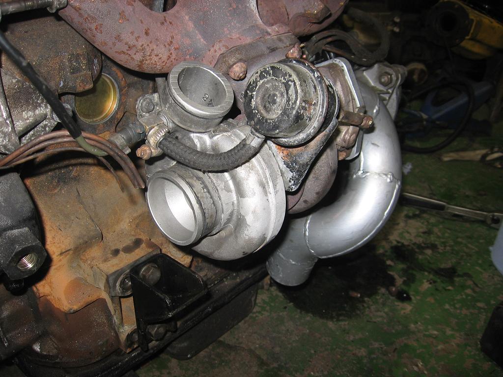
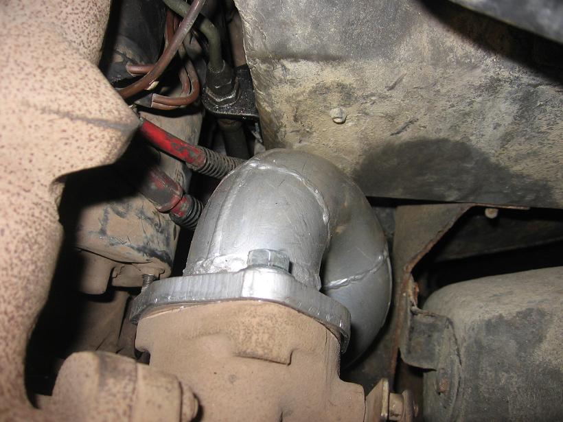
'Clocked' turbo with upward-facing outlet.
Exhaust downpipe
The Discovery uses a cast stub pipe bolted to the turbo which points in entirely the wrong direction. There is very little clearance between the turbo and the passenger side footwell, so you need a downpipe that curves down and inwards to clear the footwell and chassis rail. If you have plenty of time and good fabrication skills you can make one, but most people will find it easier to buy one. I use the downpipe sold by Steve Parker Land Rovers and have always found that these fit very well. Make sure you follow the instructions, especially the bit about relocating the clutch pipe and shortening the downpipe mounting studs. If you forget to shorten the studs, you will find that in order to change the starter motor you have to remove the manifolds. Incidentally, when removing the old cast stub, since the studs need to be shortened anyway, save yourself some time and just cut the nuts off with a disc cutter. They tend to be very tight and often take the studs out with them when you try to undo them.
Steve Parker downpipe in place, showing where the clutch pipe and bracket have been relocated to the inner edge of the footwell. The battery cable isn't as close to the downpipe as it looks, but you need to make sure it is secured well out of the way.
Engine out!
Now you have done as much prep work as you can on the new engine it is time to remove the old one. You will need to remove the bonnet and radiator. Front panel will also need to come out unless you have a crane big enough to lift the engine over it. Also the exhaust front section (or the whole exhaust unless you are converting a 2.5TD). Inside - transmission tunnel, passenger side floor panel, remove the screws on the diaphragm panel (between the transmission tunnel and bulkhead) then remove enough screws on the drivers side floor panel to be able to jiggle the diaphragm panel out from underneath it. You don't need to remove the drivers side floor panel unless the footwell is rotten and you want to weld it up. Disconnect the engine wiring loom at the bulkhead (multipin connector), disconnect the battery lead from the starter and earth strap between chassis and engine block and you can take the engine out with the loom still attached. Remove the air filter housing and bracket (three M6 bolts, one of which is almost impossible to reach). Disconnect throttle cable, servo pipe, fuel lines, power steering pipes (if fitted), glowplug cable (on diesels) and anything else that needs to come off. Remove all the bellhousing nuts and the top and bottom nuts on the engine mounts, lift the engine far enough up to remove the rubber mounts, then lower it slightly, support the front of the gearbox (tall jack, or thick block of wood between gearbox and crossmember) and the engine should pull out.
Now remove the engine mounts and fit them to the new engine. On the left hand side there are two sets of holes. Discovery (and Series 2/3) uses the front set of holes. Defender uses the REAR set. The threads are probably clogged with mud and rust and will need cleaning out.
Wiring loom - it is helpful to fit this to the new engine before you drop it into the vehicle. In particular the starter solenoid wire (red/white) is very difficult to get to with the engine in the vehicle. Your old wiring loom should fit whether petrol or diesel. The only problem you might find is that on older diesels the temperature sender is at the back of the head. In this case you may need to extend the wire (green/blue) to reach the sender. White wire goes to the stop solenoid on the injection pump, white/brown to the oil pressure switch.
Alternator wiring - most Defender alternators have a plug connector, Discos use ring terminals. If using the Disco alternator you will need to cut off the plug from the wiring loom and fit (crimp or solder) ring terminals - 4mm for brown and yellow wire, 6mm for brown wire(s). On the back of the Disco alternator are three terminal posts, 4, 5 and 6mm diameter. The 5mm terminal is a sender for the Disco rev counter and can be ignored.
Clutch - petrol clutches are not as strong as diesel and should be replaced. Diesel clutches can be reused if in good condition, but I advise replacing the clutch unless it is fairly new. Or you can use the Disco clutch that came with your new engine if it is in good order. You don't want to have the engine out again for a good few years, so fit a new clutch if there is any doubt. Check the condition of the spigot bush in the back of the flywheel and replace if worn, cracked or loose. Make sure the new clutch plate is properly centralised on the flywheel. The absolute best tool for this is the end of the input shaft cut off a scrap gearbox. You can buy universal centralising tools, or the proper Land Rover tool if you are feeling flush. Some people swear by broom handles wrapped with insulating tape. Or if you are careful you can line it all up by eye. If the clutch plate is not absolutely central the end of the gearbox shaft will not be able to slide into the spigot bush and your engine will not go in.
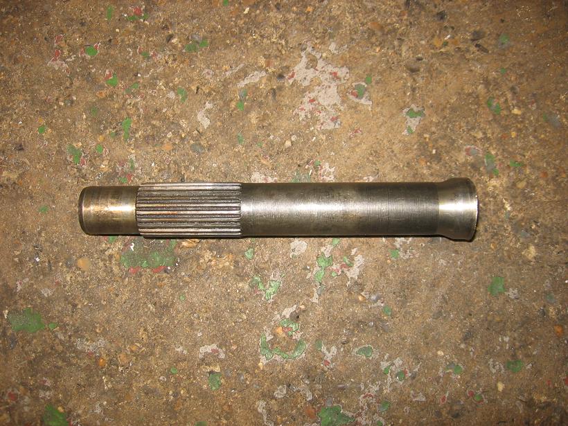
Old gearbox input shaft cut off a scrap Defender box. The perfect clutch alignment tool.
Clutch release fork - these have a habit of wearing through at the pivot. Eventually the pivot ball punches straight through the fork. You can buy strengthened clutch forks which have a steel bar welded across the back of the pivot point, or you can do it yourself with a piece of thick steel and a welder. Always replace the release bearing even if you are reusing the old clutch. Check the condition of the clutch slave cylinder and change it is it shows signs of leaking fluid. It is not that easy to get to once the engine is in the vehicle and the exhaust in place.
Having relocated the clutch pipe to clear the downpipe you will need to bleed the clutch. If you do this while the engine is out it is a one man job. Push the clutch fork all the way back into the bellhousing and secure it with a jubilee clip or similar. This pushes the slave cylinder piston back into the cylinder reducing the chance of trapping air behind the piston. You will find you can reach the clutch pedal with your left hand and the bleed nipple with your right. Keep bleeding until no more air emerges, and remember that the master cylinder has a very small reservoir, so top up every two or three pumps.
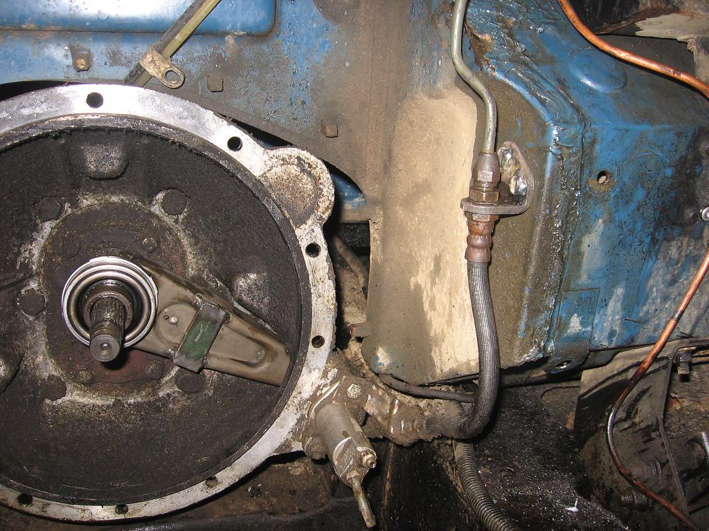
Relocated clutch pipe with new bracket. Note also strengthening bar welded across front of clutch fork.
Now things get really exciting as you can fit your new engine. Use new good quality rubber mounts - the cheap replacements are very hard and don't damp out the vibrations all that well). Make sure that you have the engine absolutely square to the gearbox before you try to engage the input shaft with the clutch plate - if the two are at an angle the engine will not slide into place and you might damage the clutch plate trying to force it in. You may also have to engage a gear and rotate the engine with a socket on the crank pulley bolt to get the splines to line up. Be careful and patient and the engine will slide into place with a satisfying clunk. Refit and tighten the bellhousing nuts, raise the engine enough to fiddle the rubber mounts into place, remove the gearbox support and carefully lower the engine onto the mounts, then refit the top and bottom nuts, washers and spring washers to the mounts. The heavy work is now over and you can start plumbing in your new engine.
Next - plumbing and wiring - click here